
A shell-and-tube heat exchanger rarely fails because the shell cracked. It fails because one tube joint leaked. A 2,000-tube bundle carries roughly 4,000 welds, most of them made inside a narrow bore where the arc cannot be seen directly, on a joint that joins thin tube wall to thick tube sheet. That is the joint automatic tube-to-tubesheet welding exists to control — and it is the joint KEPUNI has been building machines around since the first TB series head left our shop.
Three properties make this joint harder than any other weld on the exchanger, and all three are structural rather than cosmetic.
Massive heat sink. A 100 mm thick tube sheet absorbs heat far faster than a 1.2 mm tube wall through the arc. Without a programmed current ramp and a stable arc-voltage control, the weld starts cold and finishes hot: lack of fusion at the root, then burn-through at the close-out.
Blind access. The weld is made inside the tube bore, flush with or slightly recessed below the tube sheet face. The operator sees the torch, not the puddle. Every parameter that a manual welder would judge by eye — arc length, gas coverage, travel speed — has to be set by the machine and repeated identically 4,000 times.
Consequence asymmetry. One leaking joint sends the whole bundle back to hydro test, and often back to re-tubing. The cost of a re-tube is measured in weeks of downtime and normally exceeds the price of the welding system that would have prevented it. Buyers who compare quotes on machine price alone are optimising the smallest number in the equation.
Every parameter above lives in a stored program, not in the operator's hands. That is the difference between a welding position and a welding process: batches made in March and batches made in November come out the same.
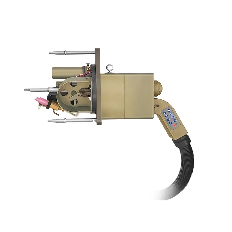
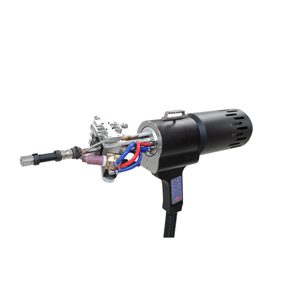
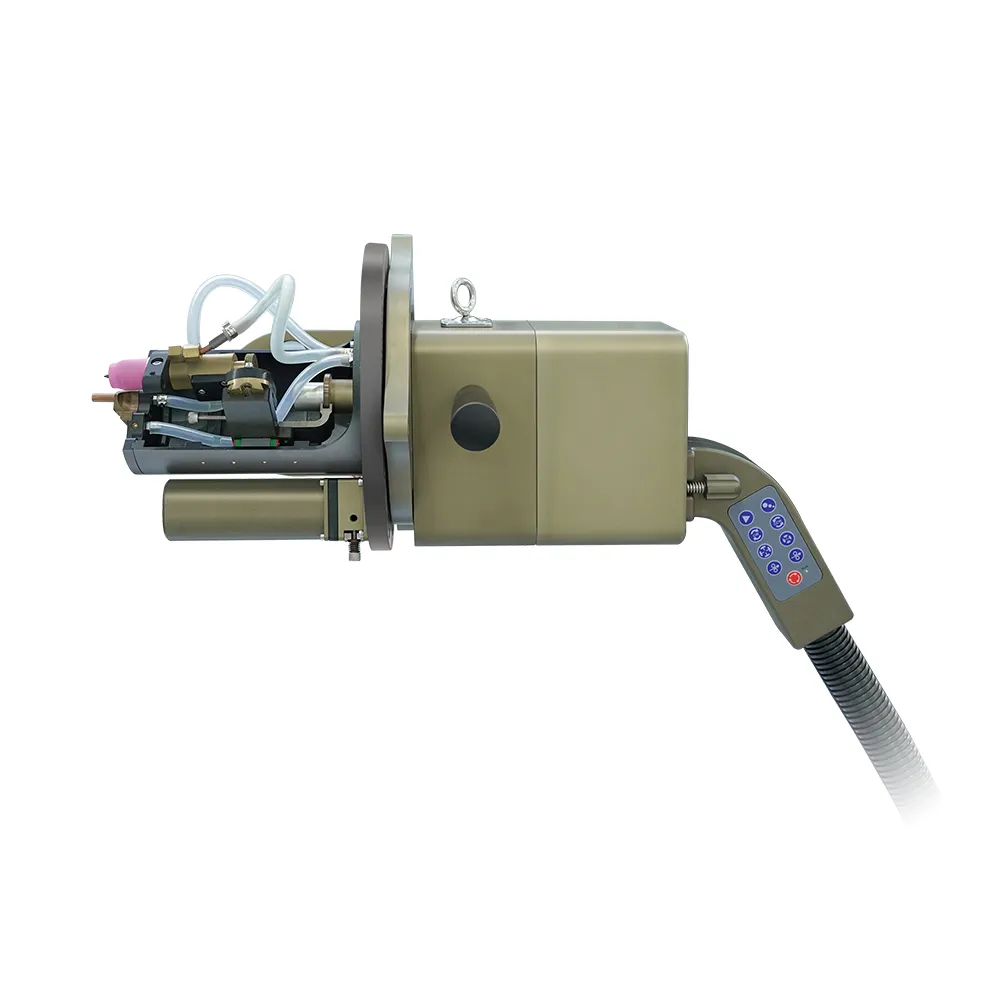
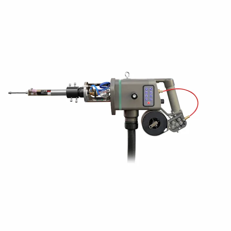
The TB series covers the range of tube sheet layouts we see in heat exchangers, boilers, condensers and feedwater heaters. Choosing between them is a question of tube diameter, tube pitch, available clearance and how much of the duty cycle you want automated.
| Model | Type | Typical fit | What it gives you |
|---|---|---|---|
| TB-35 | Tube-to-tubesheet weld head | Small-bore tubes and tight tube pitches, where a compact body is the only way in | Compact head body, pneumatic clamping, access into narrow tube lanes |
| TB-65 | Tube-to-tubesheet weld head | Standard heat exchanger and boiler tube sheets, medium to larger tube OD | Larger body and water-cooled torch option for longer continuous runs |
| TBM-65 | Automated weld head | Production tube sheets where the sequence should run without operator intervention | Automated weld sequence, integrated with the machine control and program database |
| TBS-65 | Automated weld head | Same tube range, different clamping and drive arrangement to suit the tube sheet drawing | Automated sequence with an alternative head geometry |
| TBK-65 Suspended | Suspended head | Large tube sheets where head weight must be carried off the joint | Balanced suspension so the head floats on the tube axis instead of hanging from it |
| Tube-to-Tubesheet Orbital System | Complete machine | Buyers who want the full package rather than a head for an existing power supply | Power supply, cooling, weld head, program database and operator training in one system |
TBM and TBS share the same tube range and differ in clamping and drive arrangement. Send us the tube sheet drawing — tube OD, wall thickness, pitch, ligament width and the projection dimension — and we will tell you which body fits, rather than which one is in stock.
Three joint designs appear on tube sheet drawings, and they are not interchangeable.
Design rules for these joints are set by the applicable code — ASME Section VIII Division 1 for pressure vessels, EN 13445 in Europe, GB/T 151 in China — and the welding procedure is qualified separately under ASME Section IX or ISO 15614. When the drawing and the WPS disagree, we build to the drawing and flag the conflict before the first weld.
Carbon steel and low-alloy tube sheets with carbon or stainless tubes; 304 and 316L stainless in both components; duplex 2205 and super duplex where chloride stress corrosion governs; titanium and titanium-clad tube sheets for seawater coolers and desalination; nickel alloys such as Inconel 600, 625 and Monel 400 for high-temperature and corrosive service; copper-nickel and admiralty brass for marine and condenser duty.
Each family changes the program, not just the current value. Titanium needs a far more rigorous trailing shield; duplex is sensitive to heat input and ferrite balance; copper alloys conduct heat away so aggressively that preheat and a faster ramp become part of the procedure. If a material is new to your shop, we weld a sample before the machine ships.
| Variable | What goes wrong when it drifts |
|---|---|
| Arc gap | Too long: arc wander, wide bead, lack of penetration. Too short: tungsten contamination, arc instability |
| Arc voltage control | Without AVC, tube sheet face run-out and tube end squareness convert directly into gap variation |
| Current ramp | Cold start leaves lack of fusion at the root; a hard stop leaves a crater at close-out |
| Rotation speed | Sets heat input per mm. Too fast: lack of fusion. Too slow: sagging bead and grain growth in duplex |
| Pulse parameters | Pulse ratio and frequency control bead profile and penetration; wrong pulse shows up as scalloped bead edges |
| Shielding and purge | Insufficient purge gives oxidised, discoloured beads — the single most common penetrant failure |
| Electrode condition | A blunt or contaminated tungsten changes arc shape; a chipped tip changes it unpredictably |
| Cleanliness | Cutting oil, marker pen, moisture or oxide in the joint produces porosity that no parameter change will fix |
| Defect | Usual cause | How the process controls it |
|---|---|---|
| Lack of fusion at root | Cold start, gap too long, contaminated surface | Programmed upslope, mechanical gap setting, defined cleaning standard |
| Porosity | Inadequate purge, oil or moisture in the joint | Timed pre-flow, sealed purge chamber, pre-weld wipe down |
| Burn-through | Excess current on thin wall, heat sink underestimated | Current ramp with close-out taper, validated program per tube size |
| Crater crack | Arc stops without overlap | 15–20° overlap past the start point, controlled downslope |
| Oxidised / discoloured bead | Purge lost mid-weld, trailing shield too short | Flow-monitored purge, trailing shield sized to the joint |
A tube-to-tubesheet welding procedure is qualified like any other procedure: a pWPS, a test coupon on the same material and joint geometry, then destructive and non-destructive examination. Depending on the code and the customer specification, that means macro section, bend or nick-break, pull-out test, radiography, penetrant testing and, for hygienic or high-purity duty, helium leak testing to the specified leak rate.
Production joints are normally verified by penetrant testing on a sample basis set by the specification, with hydro test as the final gate. Machines store the weld program and the parameter trace for each joint, so the record exists before the inspector arrives — which matters when the end user's QA package requires traceability back to individual tube positions.
Our certificates and qualification records are available for review before order.
Shell-and-tube heat exchangers, condensers, feedwater heaters, air coolers, kettle and falling-film evaporators, waste heat boilers, steam generators and tube-sheet assemblies for chillers. The industries behind them are petrochemical and refining, power generation, HVAC and refrigeration, food and dairy processing, pharmaceutical and biotech, desalination and marine.
If your product is a boiler rather than an exchanger, the same heads run on boiler tube sheets; if the tube sheet sits inside a sanitary or high-purity circuit, see our heat exchanger application notes for the surface and purge requirements that apply.
Nine answers let us size the system and quote it without a second round of questions:
Send those and you get a head recommendation, a program starting point based on comparable jobs, and a price — usually the same working day.
| Hand TIG | Automatic tube-to-tubesheet | |
|---|---|---|
| Consistency | Depends on the individual welder and the hour of the shift | Identical program for every joint in the bundle |
| Speed | Skilled operator, frequently paused for repositioning | Continuous rotation, no repositioning within the bore |
| Skill required | Years of tube sheet experience | Operator training measured in days |
| Rework rate | Rises sharply on small-bore and deep-set joints | Controlled by program validation rather than operator judgement |
| Traceability | Paper record at best | Stored program and parameter trace per joint |
| Best use | Repair work, odd geometries, single joints | Production bundles, repeated orders, code-critical work |
Tube-to-tube welding joins one tube end to another tube end, as in a pipeline or a superheater element. Tube-to-tubesheet welding joins a tube to a hole in a thick plate — the joint that seals a shell-and-tube exchanger. The second is a dissimilar-thickness joint made inside a bore, so it needs a different head geometry, a different gas path and a different program.
Usually yes, with the appropriate head. The power supply and controller are common across our orbital range; the head carries the geometry. Shops that build both exchangers and pipe spools typically buy one controller and two heads.
The model number denotes the head size class, so TB-35 and TB-65 cover different tube OD ranges with different body diameters. Because tube OD and pitch together decide whether a head physically fits between neighbouring tubes, we confirm the range against your tube sheet drawing rather than quoting a single figure.
For a fusion (seal) weld, the tube is normally lightly expanded or tacked to hold position, and the weld provides leak tightness. For a strength weld, the tube is expanded or the tube hole is grooved so the weld carries load. The drawing decides; we do not substitute one for the other.
Almost always a purge problem, not a current problem. Either the pre-flow is too short, the purge is leaking out of the bore, or the trailing shield is too small for the joint. Check gas flow at the head, not at the regulator, and confirm the bore is sealed on the far side.
A typical joint welds in well under a minute of arc time. Real throughput is set by indexing between tubes — moving the head, locating the next bore and starting the program — not by the weld itself. That is why the suspended and automated heads matter on large bundles.
A test coupon of the same tube sheet material, tube material, wall thickness and joint design, welded with the production program, then examined to your code and customer specification. We support the coupon, the parameter record and the documentation package; the qualification itself is issued by your welding engineer or an accredited body.
Depends on the model and the duty cycle. Send us the supply available in your shop and the tube size, and we will confirm which configuration fits rather than shipping a machine that trips the breaker on the third bundle.
Tube OD, wall thickness, pitch and joint design are enough for us to size the machine, propose a starting weld program and quote. If you are replacing hand TIG on an existing bundle, we will also tell you what the first week of changeover looks like.
Request a tube sheet welding review